

Design and calculation of finned heat exchanger in refrigerant system
The heat transfer coefficient of the heat exchanger of the refrigerant system can be calculated through a series of experimental correlations. This is because there is a heat transfer process in which gas and liquid coexist in this type of heat exchanger, so it is relatively complicated. Now, experimental correlations are often used for calculation. Previous heat transfer studies were mostly for commonly used refrigerants, such as R12, R22, R717, R134a, etc., while there are relatively few studies on R404A and R410A. According to the heat transfer process, the calculation formula for the heat transfer of the heat exchanger is:
 Q=KoFΔtm (W)
Q—unit heat transfer, W
Ko—heat transfer coefficient, W/(m2.C)
F—heat transfer area, m2
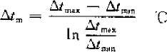
Δtm—logarithmic mean temperature difference, C
Δtmax—the maximum temperature difference between the cold and hot fluids. For the evaporator, it is the inlet air temperature-evaporation temperature; for the condenser, it is the condensation temperature-inlet air temperature.
Δtmin—the minimum temperature difference between the cold and hot fluids. For the evaporator, it is the outlet air temperature-evaporation temperature; for the condenser, it is the condensation temperature-outlet air temperature.
The calculation formula of heat transfer coefficient K is:
K = 1/(1/α1+δ/λ+1/α2)
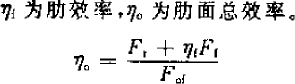
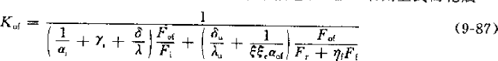
However, round tubes are used in heat exchangers, and now they all have fins (whether fin type or shell and tube type). There will be dirt on the surface of the heat exchanger, introducing the dirt coefficient. For the evaporator, there is also a moisture separation coefficient. In the design calculation, the heat transfer is generally calculated based on the outer surface of the heat exchanger. Therefore, for the finned evaporator, it is expressed as:

Kof – heat transfer coefficient based on the external surface, W/(m2.C)
αi—heat transfer coefficient inside the tube, W/(m2.C)
γi—Tube inner side fouling coefficient, m2.C/kW
δ, δu—pipe wall thickness, frost layer or water film thickness, m
λ, λu—thermal conductivity of copper tube, frost or water, W/mC
ξ,ξτ—humidity analysis coefficient, considering the coefficient of air resistance increase caused by frost or water film, 0.8-0.9 (1 can be used when hydrophilic aluminum foil is used in air conditioning)
αof—heat transfer coefficient of the outer side of the tube, W/(m2.C)
Fof—surface area, m2
Fi—internal surface area, m2
Fr—Surface area of copper tube, m2
Ff—fin surface area, m2
ηf—fin efficiency,
Formula analysis:
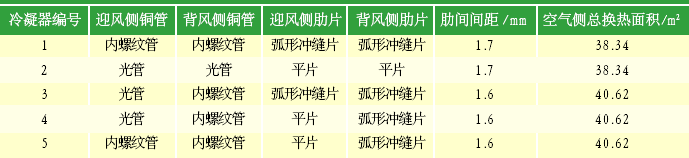
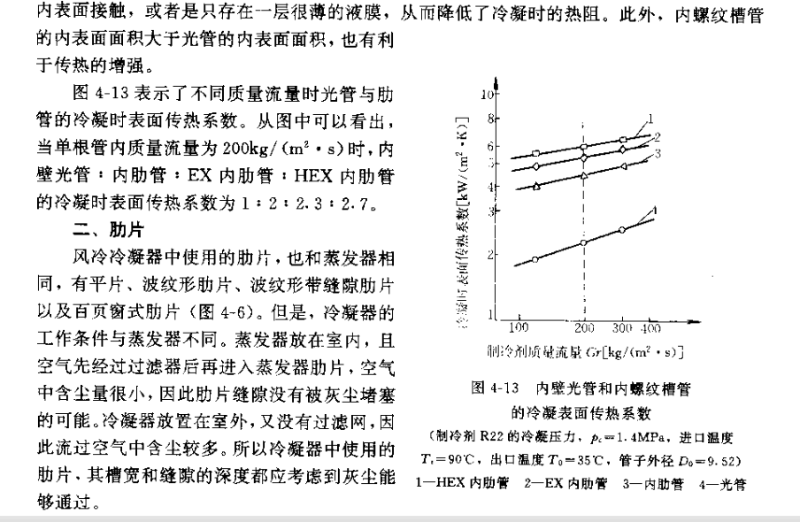
According to the collected data (see the table below) and the calculated results, the heat transfer coefficient of the smooth copper tube inside the air-conditioning condition is 2000-4000 W/
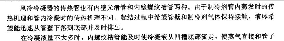
(m2.C) (R22 takes the front section, R134a takes the back section, and the experimental results show that the heat transfer performance of R134a is higher than that of R22). Because the evaporator now mostly uses internal threaded tubes, it is also necessary to multiply by an enhancement factor of 1.6-1.9.
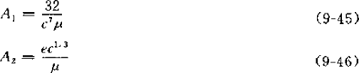
The following calculation formula comes from “Refrigeration Principles and Equipment” (Second Edition, 1996, edited by Wu Yezheng):

αi—heat transfer coefficient inside the tube
vm—mass flow rate, kg/(m2.s) di—inner diameter of copper tube, m
 A
A
![]() 1, A2- coefficient, μ- molecular weight of refrigerant
1, A2- coefficient, μ- molecular weight of refrigerant
However, for current general refrigeration products, since the mass flow rate is relatively large, the flow rate is relatively high, so they all meet this requirement, so formula (9-43) is generally used.
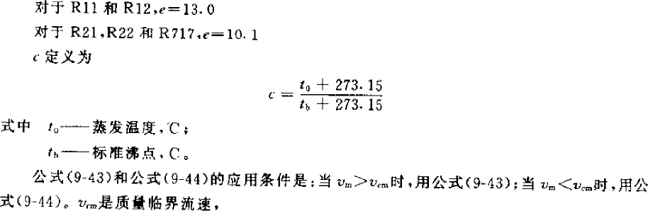
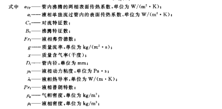
However, the above formula is not applicable to R134a. “Design Guide for Small Refrigeration Equipment” (1999, edited by Wu Yezheng) and “Principles and Equipment of Refrigeration” (3rd edition, 2010, Wu Yezheng) both cited a correlation formula proposed by Kindlikar in 1987 that has been verified by a large amount of data and has a high accuracy for R134a refrigerant. This formula can also be used for other refrigerants such as R22. After research in recent years, it has been found that this formula can also be used for the calculation of R410A evaporator :
![]()


This formula is relatively complex, requiring many parameters, and it is necessary to assume the heat flow q for iterative calculations. However, after calculation and comparison, it was found that the previous formula can be multiplied by a coefficient, which is calculated to be 1.05, so the previous formula can be used for R134a.
The heat transfer coefficient of the inner side of the tube in the refrigerator working condition is less than 1000 W/(m2.C) (R22), which is related to the mass flow rate of the refrigerant. Some researchers used the Kandlikar correlation to obtain the heat transfer characteristics of R134a under different mass flow rates (air conditioning conditions) through computer simulation, as shown in the figure below:

When designing a general evaporator, it is considered that an increase in mass flow rate will cause an increase in resistance, so the mass flow rate should not be too large. This can be analyzed together with the flow path length, and finally the appropriate mass flow rate is selected. As for the heat transfer coefficient inside the tube, the main factors affecting the heat transfer are the refrigerant properties and the refrigerant mass flow rate. From the calculation results and empirical analysis, for light tubes and flat plates, if the mass flow rate is 200-400
kg/(m2.s), then the range of the (average) heat transfer coefficient inside the tube is mainly concentrated between 2000-8000 W/(m2.C), R22 takes the front range, and R134a takes the back range.
The fouling coefficient is a fixed value based on experience. The fouling coefficient of the inner surface of the tube is 0.09×10^-3 m2.C/W. The thermal resistance of the copper tube wall is only related to the structure, and the commonly used 9.52 light tube is 8.8×10^-7, which is too small to be ignored. However, the “Guidelines for the Design of Small Refrigeration Devices” gives a thermal resistance value of 4.8×10^-3 (m2.K/W). This value includes the thermal resistance of the tube wall, the connection between the fin and the tube wall, and the thermal resistance of the tube wall.
The contact thermal resistance, the thermal resistance of dirt on the fin side, and the thermal resistance of dirt inside the tube are negligible.
There is also Fof/Fi. Air conditioners often use 9.52 tube-in-tube aluminum fins, which generally vary between 16-22 depending on the variation of the fin pitch between 1.7-2.12. As for the heat transfer coefficient outside the tube, it is mainly related to the air properties, flow rate, and heat exchanger structure. For comfort air conditioning conditions, the air
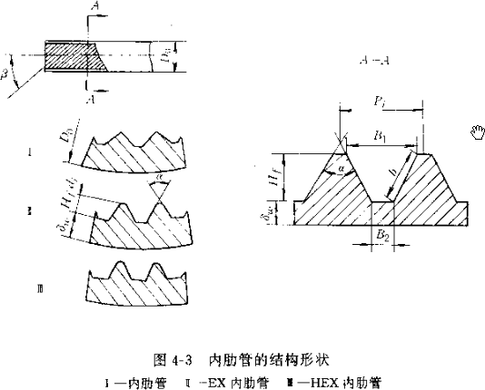
The gas parameters and flow rate are the same. The heat exchanger structure has a slight speed adjustment, but the change is not large. Therefore, 50-70 W/(m2.C) can be taken. However, this is calculated based on flat sheets. If corrugated sheets and slit sheets are used, because there is no suitable calculation formula at present, the correction coefficient can be multiplied on the basis of the flat sheet. The corrugated sheet can be 1.3, the slit sheet can be 1.8, and the corrugated slit sheet can be 2-3. This is given for the evaporator and condenser in “Refrigeration Principles and Equipment” (3rd Edition), but the two fins of the condenser are given as 1.2 and 1.6 in “Guide to the Design of Small Refrigeration Equipment”. After calculation, this is more reasonable. The condenser is calculated according to this value. In addition, a calculation formula for triangular corrugated fins is also given below for reference.
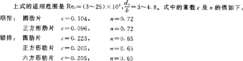
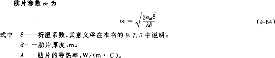
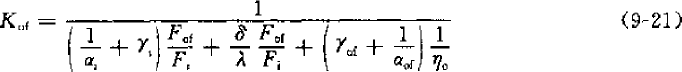
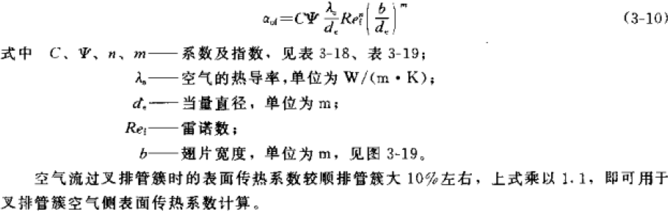
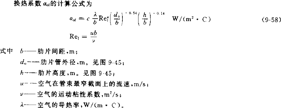 The calculation formula is as follows. The first one below is taken from “Refrigeration Principles and Equipment” (2010, third edition), but it has restrictions on use. However, the two conditions given below are contradictory. The range of Reynolds number Ref is applicable to low-temperature evaporators, but the range of d0/b is applicable to high-temperature evaporators. However, the calculation result is not much different from the second formula below, which is taken from “Guidelines for the Design of Small Refrigeration Equipment”, so both formulas can be used.


![]()
In addition, Li Wu, Tao Wenquan and others in China summarized the heat transfer correlation of triangular corrugated fins:
⎛ s ⎞0.0935 ⎛ N s ⎞0.1990
N u 0.687R e 0.518 ⎜ 1 ⎟
⎜2 ⎟
aad
⎝
3 ⎠
⎝ d 3 ⎠
, Nua=αo.do/λ, Nua is the Nusselt number of air; Rea is the air outside the tube
Air Reynolds number (calculation formula see 9-58 above); s1 is the fin spacing (m); S2 is the tube spacing along the air flow direction (m); d3 is the fin root diameter (m);
N is the number of tube rows, do is the outer diameter of the tube (m), and λ is the thermal conductivity of air (W/mC).
Frost layer does not exist in air conditioners, so it is taken as 0, and the frost layer correction coefficient wins. The air conditioning moisture analysis coefficient ξ is generally between 1.2-1.6. The air conditioning evaporator can reach 1.6 under standard working conditions. The fresh air can be taken as 2.0. The refrigerator is frosted, so it is only between 1-2, or directly taken as 1.0.
 Finned heat exchangers increase the heat transfer area by adding heat transfer fins to the heat exchange tube sleeve, which is called surface ribbing. This can enhance heat transfer. In the above heat transfer coefficient calculation formula, it is reflected as a coefficient of the heat transfer coefficient outside the tube, which is calculated as follows:

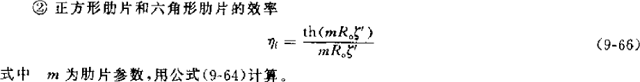
![]()
The fin efficiency is mainly related to the heat transfer coefficient of the outer side of the tube, the moisture separation coefficient, the evaporator fins and the copper tube structure size. The larger the fin spacing, the smaller the fin efficiency will be, generally 0.77-0.88, the smaller the fin spacing, the larger the fin spacing. With the fin efficiency, the total fin surface efficiency can be calculated, which is generally between 0.8-0.9 (but when calculating, the larger the fin spacing, the higher the efficiency, which seems to be a problem??)
 Fof—surface area, m2
Fr—Surface area of copper tube, m2
Ff—fin surface area, m2
For the formula taken from “Refrigeration Principles and Equipment”, it is necessary to assume the structure of the heat exchanger and use the assumed heat exchange area for iterative calculation. However, because the structural parameters can actually be calculated using unit values, only characteristic dimensions such as plate spacing, plate thickness, inner and outer diameters of copper tubes, row spacing, and tube spacing are required without knowing all the physical dimensions of the heat exchanger. Finally, the K value is calculated. In addition, considering that the evaporator outlet requires a certain degree of superheat, a design margin of 10-20% is required. For the formula taken from “Guidelines for the Design of Small Refrigeration Devices”, it is necessary to assume the heat flux density for iterative calculation, which is more cumbersome, but experiments have shown that the formula has a relatively small error.
However, from the actual calculation results, no matter what formula is used or what structure is selected, because it is a theoretical calculation, the calculated value of the light tube flat sheet is generally in the range of 40-50 W/m2.C. If corrugated sheets and internally threaded tubes are used, it can reach 60-80 W/(m2.C). The final heat exchange effect still needs to be optimized by adjusting the flow path design, so the size of the heat exchange area will also change. If the formula is derived from a more idealized model, the actual designed heat exchanger effect should be worse than the design result, so the theoretically designed heat exchanger will be smaller.
When used as a condenser, δu=0, ξ=ξτ=1, ηo=(Fr+ηf.Ff)/Fof, and the finned condenser is expressed as:
γo—Tube inner side fouling coefficient, m2.C/kW
ηo—Total efficiency of fin surface
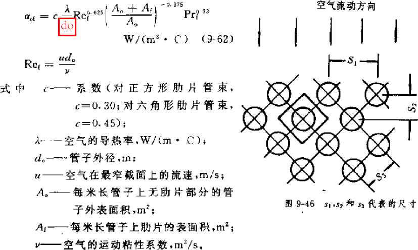
Because αo is used in the calculation of αi, αo must be calculated first. The following formula is from “Refrigeration Principles and Equipment” (1996, second edition, Wu Yezheng). This formula does not give an application range, and can be regarded as applicable to refrigerators and air-conditioning conditions. The calculated value under air-conditioning conditions is slightly smaller than the following formula. It is estimated that it is more applicable in refrigerator design because the refrigerant mass flow rate is relatively small under this condition, so the heat exchange effect is also poor. If used in air-conditioning conditions, it can be multiplied by a correction factor of 1.2. The air side of the condensation heat transfer has a higher temperature, so the heat transfer efficiency is relatively high, generally 60-80 W/(m2.C). In addition, the following formula is derived from flat sheets, so for corrugated sheets, it can be multiplied by 1.2, and for slit sheets, it can be multiplied by 1.6 as a correction factor:

The following formula comes from “Guidelines for the Design of Small Refrigeration Equipment” (1999, Wu Yezheng). Looking at the scope of application, only the structural parameters of the air conditioner and the calculation results of the physical parameters under air conditioning conditions are within the scope, so this formula is only applicable to the design calculation of air conditioning conditions:

Sf—fin distance, m; s1—windward tube distance, m; ωmax—air velocity at the narrowest cross section, m/s; υ—kinematic viscosity coefficient of air, m2/s; δf—fin thickness, m.
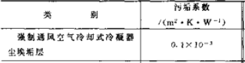
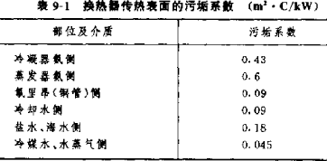
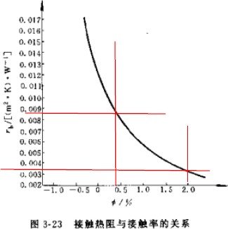
 For some thermal resistances, the condenser will be different. The “Guide to the Design of Small Refrigeration Devices” gives the air side thermal resistance (see the table above) and the contact thermal resistance, see the figure on the right. The contact thermal resistance is related to the contact rate, which is related to the processing technology of the heat exchanger. It is generally between 0.4-2%. The commonly used contact thermal resistance is
- W/m2.K, and the thermal resistance of the pipe wall is actually very small and can be ignored. The thermal resistance of the dirt in the pipe is generally ignored. However, “Refrigeration Principles and Equipment” only calculates the thermal resistance of the dirt in the pipe, but not other factors. Considering the practicality of the project, it is more in line with the actual situation to take it into account.
For the structural parameters of the condenser, such as internal and external surface areas, fin surface efficiency, etc., since they are not much different from those of the evaporator, you can refer to the evaporator.
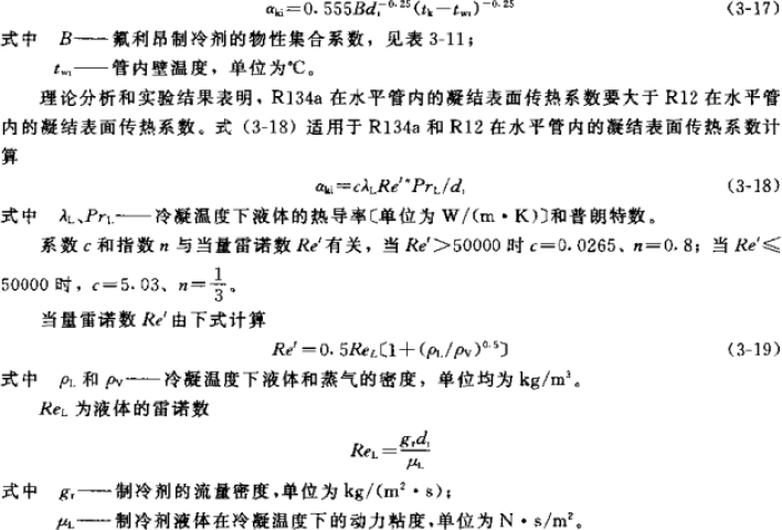
![]() After heat transfer process analysis and formula derivation, the following heat balance formula is obtained:
After heat transfer process analysis and formula derivation, the following heat balance formula is obtained:
αki—heat transfer coefficient inside the tube, W/(m2.C) ai—inner surface area of the tube, m2
αof—heat transfer coefficient of the outer side of the tube, W/(m2.C) ao—outer surface area of the tube, m2
η—Surface efficiency
tk—condensation temperature, C tw—average surface temperature of tube wall, C
tm—average inlet and outlet air temperature, C
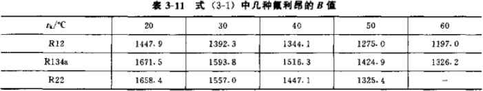
For the heat transfer coefficient inside the tube, the formula in “Refrigeration Principles and Equipment” is as follows. Because it is convenient to calculate the temperature, the former is generally used. The latter set of formulas comes from “Guidelines for the Design of Small Refrigeration Devices”. In fact, the two formulas are the same, where B=β^0.25, β is calculated, and B can be found by looking up the table. The results of the two are the same, generally ranging from 1300-1400. Δt=tk-tw, C, is the difference between the condensation temperature and the wall temperature. Substitute the following formula into the above heat balance formula. Only tw is an unknown number, which can be finally calculated. Then use the following formula to calculate the heat transfer coefficient inside the tube, which is generally 1600-2000 W/(m2.C).


The following formula is taken from the “Guide to Design of Small Refrigeration Equipment” and is a calculation formula applicable to R134a.

制冷剂系统翅片式换热器设计及计算
制冷剂系统的换热器的传热系数可以通过一系列实验关联式计算而得,这是因为在这类换热器中存在气液两相共存的换热过程,所以比较复杂,现在多用实验关联式进行计算。之前的传热研究多对于之前常用的制冷剂,如 R12,R22,R717,R134a 等,而对于 R404A 和 R410A 的,现在还比较少。按照传热过程,换热器传热量的计算公式为:
 Q=KoFΔtm (W)
Q—单位传热量,W
Ko—传热系数,W/(m2.C)
F—传热面积,m2
Δtm—对数平均温差,C
Δtmax—冷热流体间温差最大值,对于蒸发器,是入口空气温度—蒸发温度,对于冷凝器,是冷凝温度—入口空气温度。
Δtmin—冷热流体间温差最小值,对于蒸发器,是出口空气温度—蒸发温度,对于冷凝器,是冷凝温度—出口空气温度。
传热系数 K 值的计算公式为:
K=1/(1/α1+δ/λ+1/α2)
但换热器中用的都是圆管,而且现在都会带有肋片(无论是翅片式还是壳管式),换热器表面会有污垢,引入污垢系数,对于蒸发器还有析湿系数,在设计计算时,一般以换热器外表面为基准计算传热, 所以对于翅片式蒸发器表述为:

Kof–以外表面为计算基准的传热系数,W/(m2.C)
αi—管内侧换热系数,W/(m2.C)
γi—管内侧污垢系数,m2.C/kW
δ,δu—管壁厚度,霜层或水膜厚度,m
λ,λu—铜管,霜或水导热率,W/m.C
ξ,ξτ—析湿系数,考虑霜或水膜使空气阻力增加系数,0.8-0.9(空调用亲水铝泊时可取 1)
αof—管外侧换热系数,W/(m2.C)
Fof—外表面积,m2
Fi—内表面积,m2
Fr—铜管外表面积,m2
Ff—肋片表面积,m2
ηf—肋片效率,
公式分析:
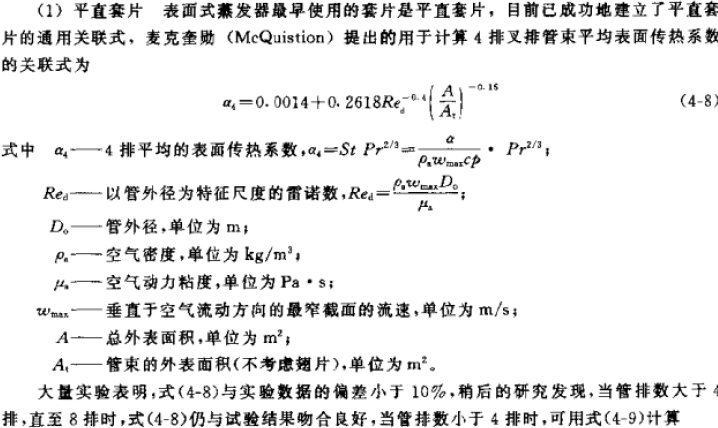
从收集的数据(见后表)及计算的结果来看,空调工况的光滑铜管内侧换热系数在 2000-4000 W/
(m2.C)(R22 取前段,R134a 取后段,实验结果表明,R134a 的换热性能比 R22 高)之间。因为现在蒸发器多使用内螺纹管,因此还需乘以一个增强因子 1.6-1.9。
下面这个计算公式来自《制冷原理及设备》(第二版,1996,吴业正主编):

αi—管内侧换热系数
vm—质量流速,kg/(m2.s) di—铜管内径,m
 A
A

![]() 1,A2— 系 数 , μ—制冷剂的分子量
1,A2— 系 数 , μ—制冷剂的分子量
但是对于现在一般的制冷产品,因为质量流量都比较大,因此流速都比较高,所以都符合这个要求, 所以一般都用公式(9-43)
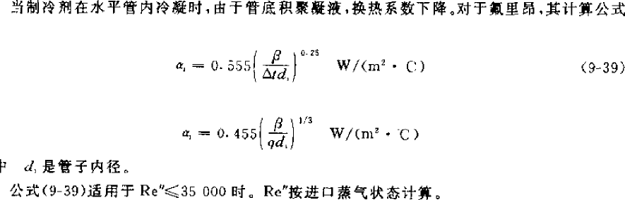
但是上面这个公式对 R134a 不太适用,《小型制冷装置设计指导》(1999,吴业正主编),《制冷原理及设备》第三版,2010,吴业正)都引用了 Kindlikar 在 1987 年提出的一个经过大量数据验证精度较高的关联式用于 R134a 制冷剂,这个公式也可用于其他制冷剂如 R22 等,经过近几年的研究发现,该公式也可用于 R410A 蒸发器的计算:

![]()


这个公式比较复杂,所需参数比较多,而且计算时需要假设热流 q 来进行迭代计算,但经过计算对比发现,可以在上一个公式的基础上再乘以一个系数,经推算为 1.05,就可以将上一个公式用于 R134a。
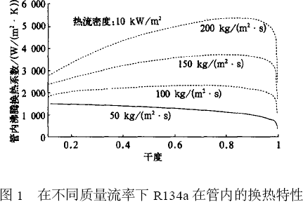
冷柜工况的管内侧换热系数不到 1000 W/(m2.C)(R22),这和制冷剂质量流速有关,有研究人员用 Kandlikar 关联式通过计算机模拟得出了 R134a 不同质量流速下的换热特征(空调工况),见下图:

而一般蒸发器设计时,考虑到质量流速的增大会引起阻力的增大,因此质量流速不宜过大,这个可结合流路长度一起分析,最后选择合适的质量流速。而对于管内侧换热系数来说,主要影响换热的是制冷剂性质和制冷剂质量流速,从计算结果和经验分析,对于光管和平片来说,如果质量流速在 200-400
kg/(m2.s),那么管内侧(平均)换热系数的范围主要集中在 2000-8000 W/(m2.C)之间,R22 取靠前区间,R134a 取靠后区间。
污垢系数根据经验值是固定值,管内表面污垢系数取 0.09×10^-3 m2.C/W,而铜管管壁导热热阻δ/λ 只和结构有关,而常用的 9.52 光管取 8.8×10^-7,这个值太小了可以忽略不计。不过在《小型制冷装置设计指导》中给出了一个热阻值 4.8×10^-3(m2.K/W),这个值包括管壁导热热阻,翅片与管壁间的接
触热阻,翅片侧污垢热阻,而管内污垢热阻忽略不计。
还有 Fof/Fi,空调常用 9.52 管套铝翅片,一般根据片距在 1.7-2.12 之间的变化在 16-22 之间变化。而对于管外侧换热系数,主要和空气性质,流速,换热器结构有关,对于舒适性空调工况而言,空
气参数,流速都一样,换热器结构稍微有些调速,但变化不大,因此可取 50-70 W/(m2.C),但这是以平片来计算的,如果是使用波纹片和条缝片,因为现在还没有合适的计算式,因此可在平片的基础上乘以修正系数,波纹片可取 1.3,条缝片可取 1.8,而波形条缝片取 2-3,这是《制冷原理及设备》(第三版)对蒸发器和冷凝器给出的,但《小型制冷装置设计指导》中对冷凝器的两种翅片给出的是 1.2 和 1.6, 经计算,这是比较合理的,下面冷凝器按此值计算。另外下面也给出了一个计算三角波纹翅片的计算公式参考。
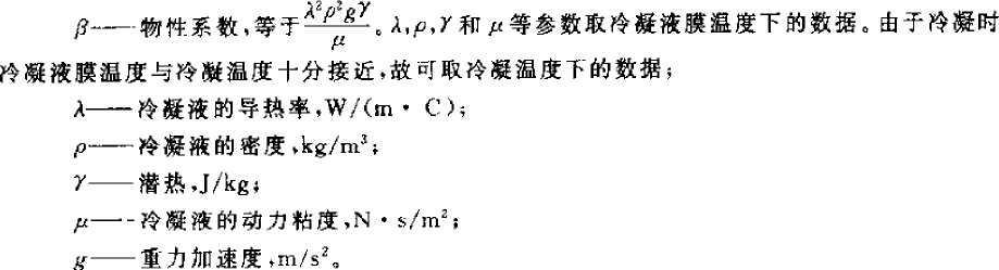
 计算公式如下,下面第一个取自《制冷原理及设备》(2010,第三版),但是使用有限制,但下面给出的两个条件是矛盾的,雷诺数 Ref 的范围适用于低温蒸发器,但 d0/b 的范围适用于高温蒸发器。但计算结果和下面第二个取自《小型制冷装置设计指导》的公式相差不大,所以两个公式都可以用。


![]()
另外,国内李妩,陶文铨等人总结了三角波纹翅片的换热关联式:
⎛ s ⎞0.0935 ⎛ N s ⎞0.1990
Nu 0.687Re0.518 ⎜ 1 ⎟
⎜2 ⎟
a a d
⎝
3 ⎠
⎝ d3 ⎠
,Nua=αo.do/λ,Nua 为空气努塞尔数;Rea 为管外空
气雷诺数(计算公式见上 9-58);s1 为翅片间距(m);S2 为沿空气流动方向管间距(m);d3 为翅根直径(m);
N 为管排数,do 为管外径(m),λ为空气导热率(W/m.C)。
霜层在空调中不存在,所以取 0,霜层修正系数取胜,空调析湿系数ξ一般在 1.2-1.6 之间,空调蒸发器标准工况下可达 1.6,新风可取 2.0,冰箱是结霜,只有 1-2 之间,或直接取 1.0。
 翅片式换热器都是通过在换热管套上换热片来增大传热面积,叫表面肋化,这样可以强化换热,在上面的传热系数计算公式中,反映为管外换热系数的一个系数,计算如下:


![]()
肋片效率主要和管外侧换热系数,析湿系数,蒸发器翅片和铜管结构尺寸有关,而翅片间距大, 肋片效率会小些,一般取 0.77-0.88,片距大取小值,片距小取大值。有了肋片效率,最后可以算出肋面总效率,一般取 0.8-0.9 之间(但是计算时片距越大,反而效率越高,好象有点问题??)
 Fof—外表面积,m2
Fr—铜管外表面积,m2
Ff—肋片表面积,m2
对于取自《制冷原理及设备》的公式,需要假设换热器的结构,使用假设换热面积来进行迭代计算, 但是因为结构参数其实可以用单位值来计算,这就只需如片距,片厚度,铜管内外径,排距,管距等特征尺寸而不需知道换热器全部物理尺寸,最终计算出 K 值,另外考虑到蒸发器出口需要一定过热度, 因此要取 10-20%的设计余量。对于取自《小型制冷装置设计指导》的公式需要假设热流密度来进行迭代计算,比较繁琐,但实验证明该公式误差比较小。
不过从实际计算结果来看,不管用什么公式还是选择什么样的结构,因为是理论计算,因此计算值光管平片一般在 40-50 W/m2.C 范围内,如果用波纹片及内螺纹管,可达 60-80 W/(m2.C),最终换热效果还需要调整流路设计来进行优化,所以换热面积大小还会变化。如果公式是从比较理想化的模型推导的,那实际设计的换热器效果应该比设计结果差,因此理论设计的换热器会偏小。
当作为冷凝器时,δu=0,ξ=ξτ=1,ηo=(Fr+ηf.Ff)/Fof,翅片式冷凝器表述为:

γo—管内侧污垢系数,m2.C/kW
ηo—肋面总效率
因为在计算αi 时要用到αo,所以要先计算αo,下面公式来自《制冷原理及设备》(1996,第二版, 吴业正),这个公式没有给出应用范围,可以看作适用冷柜和空调工况。在空调工况下的计算值比下面的公式稍小,估计在冷柜设计时比较适用,因为该工况下制冷剂质量流速相对较小,因此换热效果也差些,如果用在空调工况,可以乘以修正系数 1.2。冷凝传热的空气侧因为温度较高,所以传热效率比较高,一般在 60-80 W/(m2.C),另外以下公式是以平片得出的,因此对于波纹片,可乘以 1.2,对于条缝片,乘以 1.6,作为修正系数:
下面公式来自《小型制冷装置设计指导》(1999,吴业正),看适用范围,只有空调的结构参数及空调工况下的物性参数计算结果才在范围内,因此该公式只适用于空调工况的设计计算:


Sf—翅片片距,m;s1—迎风面管距,m;ωmax—空气在最窄截面上的流速,m/s;υ—空气的运动粘性系数,m2/s;δf—翅片厚度,m。


 对于一些热阻,冷凝器会有所不同,《小型制冷装置设计指导》给出了空气侧热阻(见上表),及接触热阻,见右图,接触热阻和接触率有关,接触率和换热器的加工工艺有关,一般在 0.4-2%之间,常用接触热阻为
- W/m2.K,而对于管壁热阻,其实还是很小,可以忽略不计。而对于管内污垢热阻,一般忽略不计。而《制冷原理及设备》里只计算管内污垢热阻,而不计算其他, 考虑到工程实用性,考虑在内会比较符合实际情况。
对于冷凝器的结构参数,如内外表面积,肋面效率等,因为和蒸发器相差不会太大,所以可以参考蒸发器。
![]() 经过传热过程分析和公式推导,得出以下热平衡公式:
经过传热过程分析和公式推导,得出以下热平衡公式:
αki—管内侧换热系数,W/(m2.C) ai—管内表面积,m2
αof—管外侧换热系数,W/(m2.C) ao—管外表面积,m2
η—表面效率
tk—冷凝温度,C tw—管壁平均表面温度,C
tm—进出口空气平均温度,C
对于管内换热系数,《制冷原理及设备》的公式如下,因为计算温度方便,一般使用前者。而后一组公式来自《小型制冷装置设计指导》,其实两个公式是一样的,其中 B=β^0.25,β是计算出来,B 可以通过查表查出来,两者结果是一样的,一般范围在 1300-1400。Δt=tk-tw,C,是冷凝温度和壁面温度之差。将下式代入上面的热平衡公式,只有 tw 是未知数,最后可求出,再用下式计算出管内侧换热系数,一般在 1600-2000 W/(m2.C)。


以下公式取自《小型制冷装置设计指导》,并给出的适用于 R134a 的计算公式。


计算出所有值后,最终可计算出 Ko,这里的设计计算没有使用迭代试算法,而是通过传热过程来计算热流密度,最终算出传热系数,对于平片光管一般在 30-40 W/(m2.C)之间,对于波纹片或条缝片,可达 40-50 W/(m2.C)。算出 Ko 值,最后可以确定冷凝器结构尺寸,一般换热面积考虑到冷凝器出口要有一定的过冷度,因此实际换热面积要比计算值大 5-10%。
虽然有文献进行过冷凝器使用内螺纹管的研究,也表明可以增强换热效果,但好象在计算研究中并不太关心这个,从实际使用看,对于小的冷凝器可能比较明显,但对于稍大的可能不太明显。

上面的计算公式都是针对早期使用的制冷剂,而 R134a 是使用了比较长时间的环保制冷剂,所以也总结出了计算关联式。对于 R410A,近十多年来一直有研究,对于蒸发器的管内沸腾换热,上面给出的 Kindlikar 关联式,实验证明计算结果误差比较小,此外还有 Christoffersen、M.Goto 以及 Koyama
(因相关资料不容易找到,所以没有列出),但有资料说在质量流量小于 400kg/m2s 时计算值偏小,对于冷凝器,Yu & Koyama 和 Shikazono 关联式与实验值比较吻合。而对于 R404A,性质与 R22 相似,在中温制冷系统中只需做一些小改动就可以代替 R22,因此在蒸发器中可以用 Kindlikar 关联式(这个公式对许多制冷剂都适用),或者用其他公式也行,但需再乘以修正系数,冷凝器是否可以借用 R22 的关联式还有待研究。对于换热器管径,一般使用的是 OD9.52 比较多,大点的有 OD12.7 和 OD15.88。而现在在家用空调中,因为对成本比较敏感,因此需要更高效率的换热效果,之前开发了内螺纹管,在研究中发现,小管径换热管效率更高,如 OD7.9,OD7.0,甚至到 OD5.0,OD4.0,越来越多应用在产品上,
特别是配上 R410A 制冷剂,因为它单位容积制冷量比较大,而且系统压力较高,因此对压降没其它制冷剂敏感。而对于新材料,之前的关联式是否能继续使用,现在还没有确切的说法,或者需要加个修正系数吧,如果有机会,可以通过试验来进行探讨。
总之,以上对内外侧换热系数及总传热系数的分析可知影响传热的主要因素,并了解翅片式换热器的基本换热设计计算。对一部分还使用旧材料及工艺的产品,还是有实用效果的,不过理论计算和实际使用还是有一定的误差,因为理论值有一部分是理想化的,而且不同的生产工艺也会影响换热效果,因此,对于常用的结构可以通过不断总结测试数据来对理论设计值进行修正,这样就可以比较接近实际应用。以下是使用一些教科书进行计算的的一些参数,以供参考。
| 蒸发器 | 冷凝器 | 蒸发器 | 蒸发器 | 冷凝器 | |
| 制冷量/ 冷凝负荷,kW | 2.664 | 7.8/9.672 | 11.6 | 15.45 | 16.54 |
| 蒸发温度/ 冷凝温度,C | -31 | 5/50 | 5 | 7.2/54 | 54 |
| 制冷剂 | R22 | R22 | R134a | R134a | R134a |
| 制冷剂质量流 速,kg/(m2.s) | 39.86 | 102.69 | 194.95 | 155.96 | |
| 进口空气温度,C | -23/90% | 35 | 27/19.5 | 27/50% | 39 |
| 出口空气温度,C | -25 | 43 | 17.5/14.6 | 17/70% | 47 |
| 对数平均温差,C | 6.96 | 10.5 | 16.8 | 14.4 | 10.5 |
| 风量,m3/h | 3147 | 3872.5 | 2427 | 2691.28 | 6564.58 |
| 迎面风速,m/s | 2.5 | 2.5 | 2.5 | 2.0 | |
| 最窄处风速,m/s | 4 | 4.6 | 4.7 | 4.3 | 3.52 |
| 翅片侧阻力/风机 功率,Pa/W | 45.3/87.5W | 28.57 | 55.19/87.5W | 500W | |
| 管外径,mm | 10 | 10 | 10 | 9.52 | 9.52 |
| 管内径,mm | 8 | 9 | 8.6 | 8.82 | 8.82 |
| 管间距/管数,mm | 28/13 | 25/18 | 25/12 | 25.4/12 | 25.4/60 |
| 排间距/排数,mm | 28/7 | 21.65/4 | 21.65/4 | 22/4 | 22/2 |
| 管布置方式 | 三角形 | 正三角形 | 正三角形 | 正三角形 | 正三角形 |
| 翅片间距/厚度, mm | 10/0.2 | 2/0.15 | 2.2/0.2 | 2.21/0.12 | 2.21/0.12 |
| 片型/管型 | 平片/光管 | 波纹片/光管 | 平片光管 | 平片/光管 | 波纹/光管 |
| 析湿系数 | 1.082 | 1.57 | 1.45 | ||
| 管内换热系数, W/(m2.C) | 654.9 | 1694 | 2671.86 | 3329.69 | 1829.25 |
| 管外换热系数, W/(m2.C) | 112.4 | 62.06 | 60.94 | 67.62 | 72.78 |
| 总传热系数, W/(m2.C) | 45.2 | 30.8 | 43.47 | 48.87 | 33.53 |
JB7659.5-1995 里列了 R22 冷凝器 Ko>30 W/(m2.C),蒸发器 Ko>40 W/(m2.C),R134a 冷凝器 Ko>25 W/(m2.C)。
翅片式换热器的设计有以下一些参数:
换热器温度参数:蒸发温度一般为 3-8C,冷凝温度一般为 45-54C(这是舒适性空调设计计算的温度值,压缩机的名义制冷量也是按这个测试出来的)。进出风温度差一般为 8-10C,低温装置中蒸发器的温差会小一点。蒸发温度及冷凝温度和出风温度的温度差一般在 10C 左右。
- 蒸发器中过热度一般为 5-10C(过热度不等同于吸气温度,在分体机或低温装置中会相差很大),冷凝器中过冷度一般为 5-8C。
- 蒸发器迎面风速一般为 1.5-3m/s,冷凝器为 2-3m/s,最窄面风速不要超过 6m/s。多数迎面风速用 2.5m/s。
 管径和厚度:主要用 D9.52×0.35mm 或 D10x0.5mm 的光管或内螺纹铜管。现在使用新制冷剂 R410a,冷凝器使用 D7.94 或 D7.0x0.35(冷凝器)或 0.3(蒸发器)mm 或
 管径和厚度:主要用 D9.52×0.35mm 或 D10x0.5mm 的光管或内螺纹铜管。现在使用新制冷剂 R410a,冷凝器使用 D7.94 或 D7.0x0.35(冷凝器)或 0.3(蒸发器)mm 或
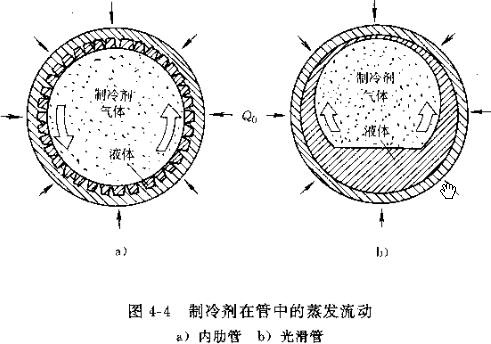
OD0.4 或 OD0.5mm 更小管径时换热效率更高。
- 行距 x 排距:多采用 25.4×22 或 25×21.65 的等边三角形叉排形式,如下图。也有用 25.4×19.5mm 的,如果使用小管径的,如 OD7.0,则多采用 21X13.6。
![]()
![]()
![]()
![]()
气流方向
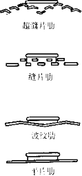
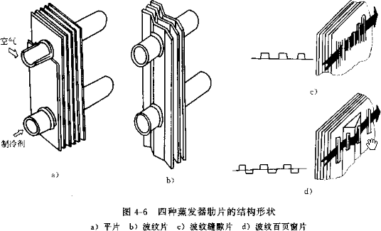
 6. 翅片:一般厚度为 0.115-0.3mm,间距为 1.8-2.5mm,蒸发器因为有冷凝水要选大点的间距,冷凝器因为是干式换热,可以选小些。冷冻装置的蒸发器考虑到结霜问题,一般在3-6mm。对于蒸发器或热泵系统的冷凝器都会采用亲水铝泊。也有些会用素片然后喷漆防锈。翅片形状主要有平片,波纹片,条缝片,或两者结合的波纹条缝片。


管路结构:蒸发器一般为 3-6 排,冷凝器为 2-6 排,因为排数太多,后面的管排换热效果会变差,如果因为结构不得不用较多排数的话,迎面风速要适当增大,以保证后面管排的风量。每一回路一般 不要超过 12-18m 左右, 蒸发器取下限值,冷凝器取上限值。不过这还要考虑制冷剂质量流量。因为太短制冷剂不能充分换热, 太长会引起较大的压降,蒸发器不要超过蒸发压力的 5%,冷凝器不要超过冷凝压力的 2%,(R22:0.03-0.05MPa),否侧会引起机组效率的降低。一般是选定翅片的参数后可算出单位长度的外表面积,然后可算出换热所需总长度,然后对于蒸发器, 因为有时在高度上有限制,或是在选用风机时考虑,有些长宽比会大些。对于冷凝器,因为结构形式很多,如 U 形,V 形,L 形,所以只要尽量大的迎风面即可。
- 流路设计:一般观点认为:对于蒸发器一般是下进上出(制冷剂蒸发成气体向上走,避免积聚在管内影响换热),然后是后进前出(和进风形成逆流)。冷凝器是上进下出,后进前出(这样冷凝的液体可以尽快利用重力流出冷凝器)。但这些只是从传热学的某一方面对传热强化来说的,实际上空调换热器的换热过程是一个复杂的过程,影响换热效率的因素也是多方面的,这里不赘述,但有一些原则可供参考:
 1。进出口也要尽量隔远一些, 避免复热。
2。不要只从一侧进,从另外一侧出,要两侧都要流过,从而避免单侧过热或过冷,从而换热不均造成换热效率下降。
3。制冷剂在管路流动时,随着干度的增加,换热效率不断提高,所以流路中后段的换热能力比前段的会高。

以下是一些公司冷凝器的回路设计,仅供参考。
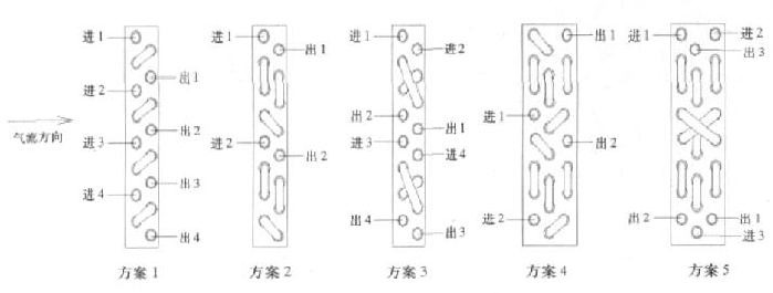
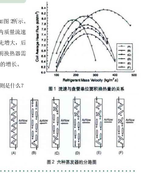
右图显示了随着制冷剂质量流速的增加,换热效果的变化,还有不同的回路设计,换热效果也不同,特别是对制冷剂质量流速的大小也有不同的要求。
 有两个观点在设计回路时可以参考:
- 对于蒸发器,随着制冷剂气体的增加, 压降和传热系数也不断增加,所以在蒸发器进口可以设计少些进口分路,在后面为了减少气体以减小压降可以再增加分路,上面的方案 D 就是这样设计。对于冷凝器则相反,开始时多些进口分路, 后面可以把冷凝后的液体汇聚减少分路,以增加流速从而强化传热,以增加过冷度,所以这部分也叫过冷管。现在有些冷凝器已经是这样设计了。因为冷
凝器一般是上进下出,所以汇集管一般在底部,也有资料说这样的强化设计也可以让热泵化霜时可能把霜化干净。
- 换热器的迎风侧和背风侧的换热效果相差比较大,以翅片间距 1.7mm 为例,风速
0.5m/s 时迎风侧换热量占总换热量的 96.3%,风速 3.0m/s 时迎风侧的换热量占总换
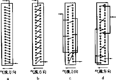
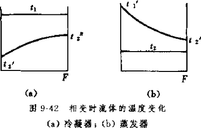
 热量的 69.2%。主要是因为传热温差的变化,以下是空气流经换热器后的温度变化图,在背风侧,温差都变小了,从而换热效果也变差。有的公司设计了以下结构的冷凝 器,以#5 为效果最好。
所以要考虑如何提高背风侧的管路的换热效率,如提高风速,降低迎风侧和换热效
率,即降低迎风侧出风温度,如上面的设计。换热器风机的选择:
选择风机首先要知道风机全压,功率和风量中的其中两个才能从风机特性曲线中选出一个比较合适的风机。
所以要计算出空气克服换热器阻力的静压,如果有送风管道的还要机外静压。
对于风量,蒸发器制冷量与风量的比值(冷风比)一般为 4.6-5.5(其实也就是进出口焓差乘以进出口平均温度下的密度再除以 3.6 得出),冷凝器负荷与风量的比值(热风比)一般
为 3.5 左右(也可以通过确定焓差计算得出),冷水机的会小一些在 2.8 左右。冷凝器阻力的计算有一些公式:
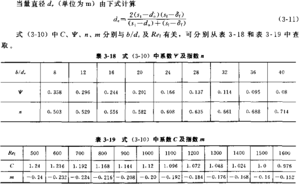
C—系数,顺排 0.0687,叉排 0.108 ![]() b/l—沿气流方向的长度,m
b/l—沿气流方向的长度,m
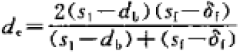
de—当量直径,公式见下,m
![]() ρ—空气密度,取进出口平均温度时的值,kg/m3
ρ—空气密度,取进出口平均温度时的值,kg/m3
u/ωmax—最窄面风速,m/s
 s1—管距,m
db— 套翅片后铜管外径,m
sf—翅片间距,m
δf—翅片厚度,m
前者是计算顺排平片冷凝器的公式,如果是叉排,还要乘以系数 1.2,如果是波纹片或者是条缝片,还要乘以 1.2,如果是蒸发器,也可以再乘以一个系数 1.2,前者算出的比后者的大 20%左右。但这只是计算气流流经换热器的摩擦阻力,在实际产品中,因为结构的原因,如斜放,或回风口与出风口成一定角度,而造成气流经过换热器各点风速不均匀的问题,这会造成局部阻力增大。而且如果气流大部分只流经一部分换热器,那么换热效率也会比较低,所以结构上要尽量减少这种情况,如果不得不这样设计,那么要考虑这部分的阻力损失。此外还有气流进出换热器,气流方向的改变,风道截面的变化等引起的局部阻力。一般经验值:
蒸发器湿工况:35-40Pa/排,干工况:30-35Pa/排; 冷凝器:20-25Pa/排。
风机全压分为动压和静压,静压又可以分为克服换热器及一些机组附件如回风格栅或过滤网(器),以及和风管的的摩擦阻力和空气流经机组时的局部阻力(风速及迎风面或出风面的变化而产生)两部分,气流通过机组以外的风管及其附件需要克服的阻力叫机外静压或余压。因为风机的动压和静压之间会互相转换,所以阻力过大可能会引起风量的减少。
用上面的公式算出换热器的风阻后,再加上机外静压,就可以得到全部静压,动压计算公式为:
ΔP’—动压,Pa
ρa—空气密度,kg/m3 ![]()
ω—出口风速,m/s
计算风机功率主要是指风机轴功率,然后可以通过传动效率(皮带传动效率为 0.95) 计算出电机输出功率。
P—风机全压,Pa
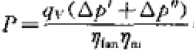
qv—空气体积流量,m3/h
Δp’—动压,Pa
Δp”—静压,Pa
ηfan—风机效率,空调用离心式风机一般为 0.5-0.6,具体要看产品。
设计示例:
设计一个 R22,10HP,制冷量为 28kW 的系统的蒸发器和冷凝器,设计参数如下:
| 蒸发温度 t0,C | 7 | 管内径 di,mm | 8.82 |
| 冷凝温度 tk,C | 54 | 管外径 do,mm | 9.52 |
| 蒸发器回风温度 t1,C | 27C/19 | 管间距 H1,mm | 25.4 |
| 蒸发器出风温度 t2,C | 17/70% | 排间距 H2,mm | 22 |
| 冷凝器回风温度 t1,C | 35 | 蒸发器翅片间距 df,mm | 2.1 |
| 冷凝器出风温度 t2,C | 45 | 蒸发器翅片间距 df,,mm | 1.9 |
| 过冷度 tsc,C | 5 | 翅片厚度δ,mm | 0.115 |
| 过热度 tsh,C | 5 | ||
| 蒸发器风量,m3/h | 5600 | 蒸发器迎面风速,m/s | |
| 冷凝器风量,m3/h | 10400 | 冷凝器迎面风速,m/s |
蒸发器的设计:
Δtm=(Δtmax—Δtmin)/ln(Δtmax/Δtmin)=((27-7)-(17-7))/ln((27-7)/(17-7))=14.4C
选 取 K=40 W/(m2.C) Q=KFΔtm (W)
F=Q/KΔt=28000/(40*14.4)=48.6m2
计算所选翅片管单位长度的外表面积:
外表面铜管面积:
S1=3.14*(do+δ*2)*(df-δ)/df=3.14*(9.52+0.115*2)*(2.1-0.115)/2.1/1000=0.0289m2
外表面翅片面积:
S2=(H1*H2-(3.14*(do+δ
*2)^2/4))/df/1000=(25.4*22-(3.14*(9.52+0.115*2)^2/4))/10^3/2.1=0.4611m2 St=S1+S2=0.0289+0.4611=0.49m2
所需管路总长度:
L=F/St=48.6/0.49=99.18m
方案 1:
可以先假设每一回路到 12m, N’=L/12=8.26, 取整为 8,设为 3 排,每排取每 4 行一个回路, 那么单排为 8*4=32 根,高度为 32*25.4=812.8mm。3 排有 N=96 根,那单根长度L’=99.18/96=1.03m, L’/H=1.23。
方案 2:
可以先假设每一回路到 10m, N’=L/10=9.9, 取整为 10,设为 3 排,每排取每 2 行一个回路, 那么单排为 10*2=20 根,高度为 20*25.4=508mm。3 排有 N=60 根,那单根长度L’=99.18/60=1.653m, L’/H=3.24。
冷凝器的设计:
Δtm=(Δtmax—Δtmin)/ln(Δtmax/Δtmin)=((54-35)-(54-45))/ln((54-35)/(54-45))=13.38C选取 K=35 W/(m2.C)
冷凝负荷 Q’=Q*1.3=28*1.3=36.4,这里 1.3 是一个经验数值,如果有压缩机的输出功率 W,那么 Q’=Q+W
Q’=KFΔtm (W) F=Q’/KΔt=36400/(35*13.38)=77.73m2
计算所选翅片管单位长度的外表面积:
外表面铜管面积:
S1=3.14*(do+δ*2)*(df-δ)/df=3.14*(9.52+0.115)*(1.9-0.115*2)/1.9/1000=0.0289m2
外表面翅片面积:
S2=(H1*H2-(3.14*(do+δ
*2)^2/4))/df/1000=(25.4*22-(3.14*(9.52+0.115*2)^2/4))/10^3/1.9=0.51m2 St=S1+S2=0.0284+0.51=0.54m2
L=F/St=77.73/0.54=143.94m
方案 1:
取每一回路为 18m,N’=143.94/18=7.997,取整为 8,结构选择 U 形,那么高度较小,取 2
排管,那么每回路每排为 4 行,那么一排共 32 行,两排共 64 根管,单根管长为
L’=143.94/64=2.249m。高度 H=32*25.4=0.812m
方案 2:
取每一回路还是 18m,N’=8,选择 L 形,那么高度要高些,选 3 排,每回路每排为 6 行, 那么一排共 48 行,三排共 144 根管,单根管长为 L’=143.94/144=0.99m。高度
H=48*25.4=1.219m。
After calculating all the values, Ko can be calculated. The design calculation here does not use an iterative trial algorithm, but calculates the heat flux density through the heat transfer process, and finally calculates the heat transfer coefficient. For flat tubes, it is generally between 30-40 W/(m2.C), and for corrugated sheets or slit sheets, it can reach 40-50 W/(m2.C). After calculating the Ko value, the condenser structure size can be determined. Generally, the heat exchange area takes into account that the condenser outlet must have a certain degree of subcooling, so the actual heat exchange area is 5-10% larger than the calculated value.
Although there are literatures that have studied the use of internally threaded tubes in condensers, and have shown that this can enhance heat transfer, it seems that this is not a big concern in computational studies. From the perspective of actual use, it may be more obvious for small condensers, but may not be so obvious for larger ones.


The above calculation formulas are for early refrigerants, and R134a is an environmentally friendly refrigerant that has been used for a long time, so calculation correlations have also been summarized. For R410A, there have been studies in the past decade. For the boiling heat transfer in the evaporator tube, the Kindlikar correlation given above has been experimentally proven to have a relatively small error in the calculation results. In addition, Christoffersen, M. Goto and Koyama
(Relevant information is not listed because it is not easy to find), but some information says that the calculated value is too small when the mass flow rate is less than 400kg/m2s. For the condenser, Yu & Koyama and Shikazono correlations are consistent with the experimental value. As for R404A, its properties are similar to R22. It can replace R22 in the medium-temperature refrigeration system with only some minor changes. Therefore, Kindlikar correlation can be used in the evaporator (this formula is applicable to many refrigerants), or other formulas can be used, but they need to be multiplied by the correction factor. Whether the condenser can borrow the R22 correlation formula remains to be studied. For the diameter of the heat exchanger tube, OD9.52 is generally used, and the larger ones are OD12.7 and OD15.88. Now, in household air conditioners, because of the sensitivity to cost, a more efficient heat exchange effect is required. Internally threaded tubes were developed before. During the research, it was found that small diameter heat exchange tubes have higher efficiency, such as OD7.9, OD7.0, and even OD5.0, OD4.0, which are increasingly used in products.
Especially with R410A refrigerant, because it has a larger cooling capacity per unit volume and a higher system pressure, it is not as sensitive to pressure drop as other refrigerants. As for new materials, there is no definite answer as to whether the previous correlation formula can continue to be used, or a correction factor needs to be added. If there is an opportunity, we can explore it through experiments.
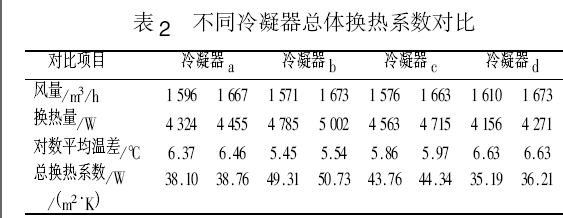
In conclusion, the above analysis of the internal and external heat transfer coefficients and the total heat transfer coefficients shows the main factors affecting heat transfer, and helps us understand the basic heat transfer design calculations for finned heat exchangers. For some products that still use old materials and processes, there are still practical effects, but there is still a certain error between theoretical calculations and actual use, because some theoretical values are idealized, and different production processes will also affect the heat transfer effect. Therefore, for commonly used structures, the theoretical design values can be corrected by constantly summarizing test data, so that they can be closer to actual applications. The following are some parameters calculated using some textbooks for reference.
| Evaporator | Condenser | Evaporator | Evaporator | Condenser | |
| Cooling capacity/ Condensing load, kW | 2.664 | 7.8/9.672 | 11.6 | 15.45 | 16.54 |
| Evaporation temperature/ Condensation temperature, C | -31 | 5/50 | 5 | 7.2/54 | 54 |
| refrigerant | R22 | R22 | R134a | R134a | R134a |
| Refrigerant mass flow Speed, kg/(m2.s) | 39.86 | 102.69 | 194.95 | 155.96 | |
| Inlet air temperature, C | -23/90% | 35 | 27/19.5 | 27/50% | 39 |
| Outlet air temperature, C | -25 | 43 | 17.5/14.6 | 17/70% | 47 |
| Log mean temperature difference, C | 6.96 | 10.5 | 16.8 | 14.4 | 10.5 |
| Air volume, m3/h | 3147 | 3872.5 | 2427 | 2691.28 | 6564.58 |
| Headwind speed, m/s | 2.5 | 2.5 | 2.5 | 2.0 | |
| Wind speed at the narrowest point, m/s | 4 | 4.6 | 4.7 | 4.3 | 3.52 |
| Fin side resistance/fan Power, Pa/W | 45.3/87.5W | 28.57 | 55.19/87.5W | 500W | |
| Tube outer diameter, mm | 10 | 10 | 10 | 9.52 | 9.52 |
| Tube inner diameter, mm | 8 | 9 | 8.6 | 8.82 | 8.82 |
| Tube spacing/number of tubes, mm | 28/13 | 25/18 | 25/12 | 25.4/12 | 25.4/60 |
| Row spacing/number of rows, mm | 28/7 | 21.65/4 | 21.65/4 | 22/4 | 22/2 |
| Pipe arrangement | triangle | Equilateral Triangle | Equilateral Triangle | Equilateral Triangle | Equilateral Triangle |
| Fin pitch/thickness, mm | 10/0.2 | 2/0.15 | 2.2/0.2 | 2.21/0.12 | 2.21/0.12 |
| Sheet type/tube type | Flat sheet/light tube | Corrugated sheet/light tube | Flat light pipe | Flat sheet/light tube | Corrugated/Light Tube |
| Moisture separation coefficient | 1.082 | 1.57 | 1.45 | ||
| Heat transfer coefficient in the tube, W/(m2.C) | 654.9 | 1694 | 2671.86 | 3329.69 | 1829.25 |
| Heat transfer coefficient outside the tube, W/(m2.C) | 112.4 | 62.06 | 60.94 | 67.62 | 72.78 |
| The overall heat transfer coefficient, W/(m2.C) | 45.2 | 30.8 | 43.47 | 48.87 | 33.53 |
JB7659.5-1995 lists the Ko of R22 condenser>30 W/(m2.C), Ko of evaporator>40 W/(m2.C), and Ko of R134a condenser>25 W/(m2.C).
The design parameters of finned heat exchanger are as follows:
Heat exchanger temperature parameters : evaporation temperature is generally 3-8C, condensation temperature is generally 45-54C (this is the temperature value calculated for comfort air conditioning design, and the nominal cooling capacity of the compressor is also tested based on this). The difference between the inlet and outlet air temperatures is generally 8-10C, and the temperature difference of the evaporator in the low-temperature device will be smaller. The temperature difference between the evaporation temperature, condensation temperature and outlet air temperature is generally around 10C.
- The superheat in the evaporator is generally 5-10C (superheat is not equivalent to the suction temperature and can vary greatly in split units or low-temperature devices), and the subcooling in the condenser is generally 5-8C.
- The wind speed on the evaporator is generally 1.5-3m/s, and the wind speed on the condenser is 2-3m/s. The wind speed on the narrowest surface should not exceed 6m/s. Most wind speeds on the face are 2.5m/s.
- Pipe diameter and thickness: mainly use D9.52×0.35mm or D10x0.5mm plain pipe or internal thread copper pipe. Now using the new refrigerant R410a, the condenser uses D7.94 or D7.0x0.35 (condenser) or 0.3 (evaporator) mm or

The heat transfer efficiency is higher when the tube diameter is smaller than OD0.4 or OD0.5mm.
- Row spacing x row spacing : 25.4×22 or 25×21.65 equilateral triangle cross-row format is often used, as shown below. 25.4×19.5mm is also used. If a small diameter tube is used, such as OD7.0, 21X13.6 is often used.
![]()
![]()
![]()
![]()
Airflow direction
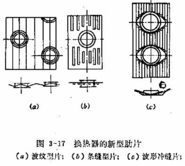 6. Fins : Generally, the thickness is 0.115-0.3mm, and the spacing is 1.8-2.5mm. For evaporators, a larger spacing is required because of condensed water, and for condensers, a smaller spacing can be selected because of dry heat exchange. For evaporators of refrigeration devices, the spacing is generally 3-6mm to take into account the problem of frosting. For evaporators or condensers of heat pump systems, hydrophilic aluminum foil is used. Some fins are made of plain sheets and then sprayed with paint to prevent rust. The main shapes of fins are flat sheets, corrugated sheets, slit sheets, or corrugated slit sheets that combine the two.

管路结构:蒸发器一般为 3-6 排,冷凝器为 2-6 排,因为排数太多,后面的管排换热效果会变差,如果因为结构不得不用较多排数的话,迎面风速要适当增大,以保证后面管排的风量。每一回路一般 不要超过 12-18m 左右, 蒸发器取下限值,冷凝器取上限值。不过这还要考虑制冷剂质量流量。因为太短制冷剂不能充分换热, 太长会引起较大的压降,蒸发器不要超过蒸发压力的 5%,冷凝器不要超过冷凝压力的 2%,(R22:0.03-0.05MPa),否侧会引起机组效率的降低。一般是选定翅片的参数后可算出单位长度的外表面积,然后可算出换热所需总长度,然后对于蒸发器, 因为有时在高度上有限制,或是在选用风机时考虑,有些长宽比会大些。对于冷凝器,因为结构形式很多,如 U 形,V 形,L 形,所以只要尽量大的迎风面即可。
- 流路设计:一般观点认为:对于蒸发器一般是下进上出(制冷剂蒸发成气体向上走,避免积聚在管内影响换热),然后是后进前出(和进风形成逆流)。冷凝器是上进下出,后进前出(这样冷凝的液体可以尽快利用重力流出冷凝器)。但这些只是从传热学的某一方面对传热强化来说的,实际上空调换热器的换热过程是一个复杂的过程,影响换热效率的因素也是多方面的,这里不赘述,但有一些原则可供参考:
 1。进出口也要尽量隔远一些, 避免复热。
2。不要只从一侧进,从另外一侧出,要两侧都要流过,从而避免单侧过热或过冷,从而换热不均造成换热效率下降。
3。制冷剂在管路流动时,随着干度的增加,换热效率不断提高,所以流路中后段的换热能力比前段的会高。

以下是一些公司冷凝器的回路设计,仅供参考。

右图显示了随着制冷剂质量流速的增加,换热效果的变化,还有不同的回路设计,换热效果也不同,特别是对制冷剂质量流速的大小也有不同的要求。
 有两个观点在设计回路时可以参考:
- 对于蒸发器,随着制冷剂气体的增加, 压降和传热系数也不断增加,所以在蒸发器进口可以设计少些进口分路,在后面为了减少气体以减小压降可以再增加分路,上面的方案 D 就是这样设计。对于冷凝器则相反,开始时多些进口分路, 后面可以把冷凝后的液体汇聚减少分路,以增加流速从而强化传热,以增加过冷度,所以这部分也叫过冷管。现在有些冷凝器已经是这样设计了。因为冷
凝器一般是上进下出,所以汇集管一般在底部,也有资料说这样的强化设计也可以让热泵化霜时可能把霜化干净。
- 换热器的迎风侧和背风侧的换热效果相差比较大,以翅片间距 1.7mm 为例,风速
0.5m/s 时迎风侧换热量占总换热量的 96.3%,风速 3.0m/s 时迎风侧的换热量占总换
 热量的 69.2%。主要是因为传热温差的变化,以下是空气流经换热器后的温度变化图,在背风侧,温差都变小了,从而换热效果也变差。有的公司设计了以下结构的冷凝 器,以#5 为效果最好。
所以要考虑如何提高背风侧的管路的换热效率,如提高风速,降低迎风侧和换热效

率,即降低迎风侧出风温度,如上面的设计。换热器风机的选择:
选择风机首先要知道风机全压,功率和风量中的其中两个才能从风机特性曲线中选出一个比较合适的风机。
所以要计算出空气克服换热器阻力的静压,如果有送风管道的还要机外静压。
对于风量,蒸发器制冷量与风量的比值(冷风比)一般为 4.6-5.5(其实也就是进出口焓差乘以进出口平均温度下的密度再除以 3.6 得出),冷凝器负荷与风量的比值(热风比)一般
为 3.5 左右(也可以通过确定焓差计算得出),冷水机的会小一些在 2.8 左右。冷凝器阻力的计算有一些公式:
C—系数,顺排 0.0687,叉排 0.108 ![]() b/l—沿气流方向的长度,m
b/l—沿气流方向的长度,m
de—当量直径,公式见下,m
![]() ρ—空气密度,取进出口平均温度时的值,kg/m3
ρ—空气密度,取进出口平均温度时的值,kg/m3
u/ωmax—最窄面风速,m/s
 s1—管距,m
db— 套翅片后铜管外径,m
sf—翅片间距,m
δf—翅片厚度,m
前者是计算顺排平片冷凝器的公式,如果是叉排,还要乘以系数 1.2,如果是波纹片或者是条缝片,还要乘以 1.2,如果是蒸发器,也可以再乘以一个系数 1.2,前者算出的比后者的大 20%左右。但这只是计算气流流经换热器的摩擦阻力,在实际产品中,因为结构的原因,如斜放,或回风口与出风口成一定角度,而造成气流经过换热器各点风速不均匀的问题,这会造成局部阻力增大。而且如果气流大部分只流经一部分换热器,那么换热效率也会比较低,所以结构上要尽量减少这种情况,如果不得不这样设计,那么要考虑这部分的阻力损失。此外还有气流进出换热器,气流方向的改变,风道截面的变化等引起的局部阻力。一般经验值:
蒸发器湿工况:35-40Pa/排,干工况:30-35Pa/排; 冷凝器:20-25Pa/排。
风机全压分为动压和静压,静压又可以分为克服换热器及一些机组附件如回风格栅或过滤网(器),以及和风管的的摩擦阻力和空气流经机组时的局部阻力(风速及迎风面或出风面的变化而产生)两部分,气流通过机组以外的风管及其附件需要克服的阻力叫机外静压或余压。因为风机的动压和静压之间会互相转换,所以阻力过大可能会引起风量的减少。
用上面的公式算出换热器的风阻后,再加上机外静压,就可以得到全部静压,动压计算公式为:
ΔP’—动压,Pa
ρa—空气密度,kg/m3 ![]()
ω—出口风速,m/s
计算风机功率主要是指风机轴功率,然后可以通过传动效率(皮带传动效率为 0.95) 计算出电机输出功率。
P—风机全压,Pa

qv—空气体积流量,m3/h
Δp’—动压,Pa
Δp”—静压,Pa
ηfan—风机效率,空调用离心式风机一般为 0.5-0.6,具体要看产品。
设计示例:
设计一个 R22,10HP,制冷量为 28kW 的系统的蒸发器和冷凝器,设计参数如下:
| 蒸发温度 t0,C | 7 | 管内径 di,mm | 8.82 |
| 冷凝温度 tk,C | 54 | 管外径 do,mm | 9.52 |
| 蒸发器回风温度 t1,C | 27C/19 | 管间距 H1,mm | 25.4 |
| 蒸发器出风温度 t2,C | 17/70% | 排间距 H2,mm | 22 |
| 冷凝器回风温度 t1,C | 35 | 蒸发器翅片间距 df,mm | 2.1 |
| 冷凝器出风温度 t2,C | 45 | 蒸发器翅片间距 df,,mm | 1.9 |
| 过冷度 tsc,C | 5 | 翅片厚度δ,mm | 0.115 |
| 过热度 tsh,C | 5 | ||
| 蒸发器风量,m3/h | 5600 | 蒸发器迎面风速,m/s | |
| 冷凝器风量,m3/h | 10400 | 冷凝器迎面风速,m/s |
蒸发器的设计:
Δtm=(Δtmax—Δtmin)/ln(Δtmax/Δtmin)=((27-7)-(17-7))/ln((27-7)/(17-7))=14.4C
选 取 K=40 W/(m2.C) Q=KFΔtm (W)
F=Q/KΔt=28000/(40*14.4)=48.6m2
计算所选翅片管单位长度的外表面积:
外表面铜管面积:
S1=3.14*(do+δ*2)*(df-δ)/df=3.14*(9.52+0.115*2)*(2.1-0.115)/2.1/1000=0.0289m2
外表面翅片面积:
S2=(H1*H2-(3.14*(do+δ
*2)^2/4))/df/1000=(25.4*22-(3.14*(9.52+0.115*2)^2/4))/10^3/2.1=0.4611m2 St=S1+S2=0.0289+0.4611=0.49m2
所需管路总长度:
L=F/St=48.6/0.49=99.18m
方案 1:
可以先假设每一回路到 12m, N’=L/12=8.26, 取整为 8,设为 3 排,每排取每 4 行一个回路, 那么单排为 8*4=32 根,高度为 32*25.4=812.8mm。3 排有 N=96 根,那单根长度L’=99.18/96=1.03m, L’/H=1.23。
方案 2:
可以先假设每一回路到 10m, N’=L/10=9.9, 取整为 10,设为 3 排,每排取每 2 行一个回路, 那么单排为 10*2=20 根,高度为 20*25.4=508mm。3 排有 N=60 根,那单根长度L’=99.18/60=1.653m, L’/H=3.24。
冷凝器的设计:
Δtm=(Δtmax—Δtmin)/ln(Δtmax/Δtmin)=((54-35)-(54-45))/ln((54-35)/(54-45))=13.38C选取 K=35 W/(m2.C)
冷凝负荷 Q’=Q*1.3=28*1.3=36.4,这里 1.3 是一个经验数值,如果有压缩机的输出功率 W,那么 Q’=Q+W
Q’=KFΔtm (W) F=Q’/KΔt=36400/(35*13.38)=77.73m2
计算所选翅片管单位长度的外表面积:
外表面铜管面积:
S1=3.14*(do+δ*2)*(df-δ)/df=3.14*(9.52+0.115)*(1.9-0.115*2)/1.9/1000=0.0289m2
外表面翅片面积:
S2=(H1*H2-(3.14*(do+δ
*2)^2/4))/df/1000=(25.4*22-(3.14*(9.52+0.115*2)^2/4))/10^3/1.9=0.51m2 St=S1+S2=0.0284+0.51=0.54m2
L=F/St=77.73/0.54=143.94m
方案 1:
取每一回路为 18m,N’=143.94/18=7.997,取整为 8,结构选择 U 形,那么高度较小,取 2
排管,那么每回路每排为 4 行,那么一排共 32 行,两排共 64 根管,单根管长为
L’=143.94/64=2.249m。高度 H=32*25.4=0.812m
方案 2:
取每一回路还是 18m,N’=8,选择 L 形,那么高度要高些,选 3 排,每回路每排为 6 行, 那么一排共 48 行,三排共 144 根管,单根管长为 L’=143.94/144=0.99m。高度
H=48*25.4=1.219m。
制冷剂系统翅片式换热器设计及计算
制冷剂系统的换热器的传热系数可以通过一系列实验关联式计算而得,这是因为在这类换热器中存在气液两相共存的换热过程,所以比较复杂,现在多用实验关联式进行计算。之前的传热研究多对于之前常用的制冷剂,如 R12,R22,R717,R134a 等,而对于 R404A 和 R410A 的,现在还比较少。按照传热过程,换热器传热量的计算公式为:
 Q=KoFΔtm (W)
Q—单位传热量,W
Ko—传热系数,W/(m2.C)
F—传热面积,m2
Δtm—对数平均温差,C
Δtmax—冷热流体间温差最大值,对于蒸发器,是入口空气温度—蒸发温度,对于冷凝器,是冷凝温度—入口空气温度。
Δtmin—冷热流体间温差最小值,对于蒸发器,是出口空气温度—蒸发温度,对于冷凝器,是冷凝温度—出口空气温度。
传热系数 K 值的计算公式为:
K=1/(1/α1+δ/λ+1/α2)
但换热器中用的都是圆管,而且现在都会带有肋片(无论是翅片式还是壳管式),换热器表面会有污垢,引入污垢系数,对于蒸发器还有析湿系数,在设计计算时,一般以换热器外表面为基准计算传热, 所以对于翅片式蒸发器表述为:
Kof–以外表面为计算基准的传热系数,W/(m2.C)
αi—管内侧换热系数,W/(m2.C)
γi—管内侧污垢系数,m2.C/kW
δ,δu—管壁厚度,霜层或水膜厚度,m
λ,λu—铜管,霜或水导热率,W/m.C
ξ,ξτ—析湿系数,考虑霜或水膜使空气阻力增加系数,0.8-0.9(空调用亲水铝泊时可取 1)
αof—管外侧换热系数,W/(m2.C)
Fof—外表面积,m2
Fi—内表面积,m2
Fr—铜管外表面积,m2
Ff—肋片表面积,m2
ηf—肋片效率,
公式分析:
从收集的数据(见后表)及计算的结果来看,空调工况的光滑铜管内侧换热系数在 2000-4000 W/
(m2.C)(R22 取前段,R134a 取后段,实验结果表明,R134a 的换热性能比 R22 高)之间。因为现在蒸发器多使用内螺纹管,因此还需乘以一个增强因子 1.6-1.9。
下面这个计算公式来自《制冷原理及设备》(第二版,1996,吴业正主编):

αi—管内侧换热系数
vm—质量流速,kg/(m2.s) di—铜管内径,m
 A
A

![]() 1,A2— 系 数 , μ—制冷剂的分子量
1,A2— 系 数 , μ—制冷剂的分子量
但是对于现在一般的制冷产品,因为质量流量都比较大,因此流速都比较高,所以都符合这个要求, 所以一般都用公式(9-43)
但是上面这个公式对 R134a 不太适用,《小型制冷装置设计指导》(1999,吴业正主编),《制冷原理及设备》第三版,2010,吴业正)都引用了 Kindlikar 在 1987 年提出的一个经过大量数据验证精度较高的关联式用于 R134a 制冷剂,这个公式也可用于其他制冷剂如 R22 等,经过近几年的研究发现,该公式也可用于 R410A 蒸发器的计算:

![]()
这个公式比较复杂,所需参数比较多,而且计算时需要假设热流 q 来进行迭代计算,但经过计算对比发现,可以在上一个公式的基础上再乘以一个系数,经推算为 1.05,就可以将上一个公式用于 R134a。
冷柜工况的管内侧换热系数不到 1000 W/(m2.C)(R22),这和制冷剂质量流速有关,有研究人员用 Kandlikar 关联式通过计算机模拟得出了 R134a 不同质量流速下的换热特征(空调工况),见下图:


而一般蒸发器设计时,考虑到质量流速的增大会引起阻力的增大,因此质量流速不宜过大,这个可结合流路长度一起分析,最后选择合适的质量流速。而对于管内侧换热系数来说,主要影响换热的是制冷剂性质和制冷剂质量流速,从计算结果和经验分析,对于光管和平片来说,如果质量流速在 200-400
kg/(m2.s),那么管内侧(平均)换热系数的范围主要集中在 2000-8000 W/(m2.C)之间,R22 取靠前区间,R134a 取靠后区间。
污垢系数根据经验值是固定值,管内表面污垢系数取 0.09×10^-3 m2.C/W,而铜管管壁导热热阻δ/λ 只和结构有关,而常用的 9.52 光管取 8.8×10^-7,这个值太小了可以忽略不计。不过在《小型制冷装置设计指导》中给出了一个热阻值 4.8×10^-3(m2.K/W),这个值包括管壁导热热阻,翅片与管壁间的接
触热阻,翅片侧污垢热阻,而管内污垢热阻忽略不计。
还有 Fof/Fi,空调常用 9.52 管套铝翅片,一般根据片距在 1.7-2.12 之间的变化在 16-22 之间变化。而对于管外侧换热系数,主要和空气性质,流速,换热器结构有关,对于舒适性空调工况而言,空
气参数,流速都一样,换热器结构稍微有些调速,但变化不大,因此可取 50-70 W/(m2.C),但这是以平片来计算的,如果是使用波纹片和条缝片,因为现在还没有合适的计算式,因此可在平片的基础上乘以修正系数,波纹片可取 1.3,条缝片可取 1.8,而波形条缝片取 2-3,这是《制冷原理及设备》(第三版)对蒸发器和冷凝器给出的,但《小型制冷装置设计指导》中对冷凝器的两种翅片给出的是 1.2 和 1.6, 经计算,这是比较合理的,下面冷凝器按此值计算。另外下面也给出了一个计算三角波纹翅片的计算公式参考。
 计算公式如下,下面第一个取自《制冷原理及设备》(2010,第三版),但是使用有限制,但下面给出的两个条件是矛盾的,雷诺数 Ref 的范围适用于低温蒸发器,但 d0/b 的范围适用于高温蒸发器。但计算结果和下面第二个取自《小型制冷装置设计指导》的公式相差不大,所以两个公式都可以用。


![]()
另外,国内李妩,陶文铨等人总结了三角波纹翅片的换热关联式:
⎛ s ⎞0.0935 ⎛ N s ⎞0.1990
Nu 0.687Re0.518 ⎜ 1 ⎟
⎜2 ⎟
a a d
⎝
3 ⎠
⎝ d3 ⎠
,Nua=αo.do/λ,Nua 为空气努塞尔数;Rea 为管外空
气雷诺数(计算公式见上 9-58);s1 为翅片间距(m);S2 为沿空气流动方向管间距(m);d3 为翅根直径(m);
N 为管排数,do 为管外径(m),λ为空气导热率(W/m.C)。
霜层在空调中不存在,所以取 0,霜层修正系数取胜,空调析湿系数ξ一般在 1.2-1.6 之间,空调蒸发器标准工况下可达 1.6,新风可取 2.0,冰箱是结霜,只有 1-2 之间,或直接取 1.0。
 翅片式换热器都是通过在换热管套上换热片来增大传热面积,叫表面肋化,这样可以强化换热,在上面的传热系数计算公式中,反映为管外换热系数的一个系数,计算如下:


![]()
肋片效率主要和管外侧换热系数,析湿系数,蒸发器翅片和铜管结构尺寸有关,而翅片间距大, 肋片效率会小些,一般取 0.77-0.88,片距大取小值,片距小取大值。有了肋片效率,最后可以算出肋面总效率,一般取 0.8-0.9 之间(但是计算时片距越大,反而效率越高,好象有点问题??)
 Fof—外表面积,m2
Fr—铜管外表面积,m2
Ff—肋片表面积,m2
对于取自《制冷原理及设备》的公式,需要假设换热器的结构,使用假设换热面积来进行迭代计算, 但是因为结构参数其实可以用单位值来计算,这就只需如片距,片厚度,铜管内外径,排距,管距等特征尺寸而不需知道换热器全部物理尺寸,最终计算出 K 值,另外考虑到蒸发器出口需要一定过热度, 因此要取 10-20%的设计余量。对于取自《小型制冷装置设计指导》的公式需要假设热流密度来进行迭代计算,比较繁琐,但实验证明该公式误差比较小。
不过从实际计算结果来看,不管用什么公式还是选择什么样的结构,因为是理论计算,因此计算值光管平片一般在 40-50 W/m2.C 范围内,如果用波纹片及内螺纹管,可达 60-80 W/(m2.C),最终换热效果还需要调整流路设计来进行优化,所以换热面积大小还会变化。如果公式是从比较理想化的模型推导的,那实际设计的换热器效果应该比设计结果差,因此理论设计的换热器会偏小。
当作为冷凝器时,δu=0,ξ=ξτ=1,ηo=(Fr+ηf.Ff)/Fof,翅片式冷凝器表述为:

γo—管内侧污垢系数,m2.C/kW
ηo—肋面总效率
因为在计算αi 时要用到αo,所以要先计算αo,下面公式来自《制冷原理及设备》(1996,第二版, 吴业正),这个公式没有给出应用范围,可以看作适用冷柜和空调工况。在空调工况下的计算值比下面的公式稍小,估计在冷柜设计时比较适用,因为该工况下制冷剂质量流速相对较小,因此换热效果也差些,如果用在空调工况,可以乘以修正系数 1.2。冷凝传热的空气侧因为温度较高,所以传热效率比较高,一般在 60-80 W/(m2.C),另外以下公式是以平片得出的,因此对于波纹片,可乘以 1.2,对于条缝片,乘以 1.6,作为修正系数:

下面公式来自《小型制冷装置设计指导》(1999,吴业正),看适用范围,只有空调的结构参数及空调工况下的物性参数计算结果才在范围内,因此该公式只适用于空调工况的设计计算:


Sf—翅片片距,m;s1—迎风面管距,m;ωmax—空气在最窄截面上的流速,m/s;υ—空气的运动粘性系数,m2/s;δf—翅片厚度,m。


 对于一些热阻,冷凝器会有所不同,《小型制冷装置设计指导》给出了空气侧热阻(见上表),及接触热阻,见右图,接触热阻和接触率有关,接触率和换热器的加工工艺有关,一般在 0.4-2%之间,常用接触热阻为
- W/m2.K,而对于管壁热阻,其实还是很小,可以忽略不计。而对于管内污垢热阻,一般忽略不计。而《制冷原理及设备》里只计算管内污垢热阻,而不计算其他, 考虑到工程实用性,考虑在内会比较符合实际情况。
对于冷凝器的结构参数,如内外表面积,肋面效率等,因为和蒸发器相差不会太大,所以可以参考蒸发器。
![]() 经过传热过程分析和公式推导,得出以下热平衡公式:
经过传热过程分析和公式推导,得出以下热平衡公式:
αki—管内侧换热系数,W/(m2.C) ai—管内表面积,m2
αof—管外侧换热系数,W/(m2.C) ao—管外表面积,m2
η—表面效率
tk—冷凝温度,C tw—管壁平均表面温度,C
tm—进出口空气平均温度,C
对于管内换热系数,《制冷原理及设备》的公式如下,因为计算温度方便,一般使用前者。而后一组公式来自《小型制冷装置设计指导》,其实两个公式是一样的,其中 B=β^0.25,β是计算出来,B 可以通过查表查出来,两者结果是一样的,一般范围在 1300-1400。Δt=tk-tw,C,是冷凝温度和壁面温度之差。将下式代入上面的热平衡公式,只有 tw 是未知数,最后可求出,再用下式计算出管内侧换热系数,一般在 1600-2000 W/(m2.C)。

以下公式取自《小型制冷装置设计指导》,并给出的适用于 R134a 的计算公式。

计算出所有值后,最终可计算出 Ko,这里的设计计算没有使用迭代试算法,而是通过传热过程来计算热流密度,最终算出传热系数,对于平片光管一般在 30-40 W/(m2.C)之间,对于波纹片或条缝片,可达 40-50 W/(m2.C)。算出 Ko 值,最后可以确定冷凝器结构尺寸,一般换热面积考虑到冷凝器出口要有一定的过冷度,因此实际换热面积要比计算值大 5-10%。
虽然有文献进行过冷凝器使用内螺纹管的研究,也表明可以增强换热效果,但好象在计算研究中并不太关心这个,从实际使用看,对于小的冷凝器可能比较明显,但对于稍大的可能不太明显。

上面的计算公式都是针对早期使用的制冷剂,而 R134a 是使用了比较长时间的环保制冷剂,所以也总结出了计算关联式。对于 R410A,近十多年来一直有研究,对于蒸发器的管内沸腾换热,上面给出的 Kindlikar 关联式,实验证明计算结果误差比较小,此外还有 Christoffersen、M.Goto 以及 Koyama
(因相关资料不容易找到,所以没有列出),但有资料说在质量流量小于 400kg/m2s 时计算值偏小,对于冷凝器,Yu & Koyama 和 Shikazono 关联式与实验值比较吻合。而对于 R404A,性质与 R22 相似,在中温制冷系统中只需做一些小改动就可以代替 R22,因此在蒸发器中可以用 Kindlikar 关联式(这个公式对许多制冷剂都适用),或者用其他公式也行,但需再乘以修正系数,冷凝器是否可以借用 R22 的关联式还有待研究。对于换热器管径,一般使用的是 OD9.52 比较多,大点的有 OD12.7 和 OD15.88。而现在在家用空调中,因为对成本比较敏感,因此需要更高效率的换热效果,之前开发了内螺纹管,在研究中发现,小管径换热管效率更高,如 OD7.9,OD7.0,甚至到 OD5.0,OD4.0,越来越多应用在产品上,
特别是配上 R410A 制冷剂,因为它单位容积制冷量比较大,而且系统压力较高,因此对压降没其它制冷剂敏感。而对于新材料,之前的关联式是否能继续使用,现在还没有确切的说法,或者需要加个修正系数吧,如果有机会,可以通过试验来进行探讨。
总之,以上对内外侧换热系数及总传热系数的分析可知影响传热的主要因素,并了解翅片式换热器的基本换热设计计算。对一部分还使用旧材料及工艺的产品,还是有实用效果的,不过理论计算和实际使用还是有一定的误差,因为理论值有一部分是理想化的,而且不同的生产工艺也会影响换热效果,因此,对于常用的结构可以通过不断总结测试数据来对理论设计值进行修正,这样就可以比较接近实际应用。以下是使用一些教科书进行计算的的一些参数,以供参考。
| 蒸发器 | 冷凝器 | 蒸发器 | 蒸发器 | 冷凝器 | |
| 制冷量/ 冷凝负荷,kW | 2.664 | 7.8/9.672 | 11.6 | 15.45 | 16.54 |
| 蒸发温度/ 冷凝温度,C | -31 | 5/50 | 5 | 7.2/54 | 54 |
| 制冷剂 | R22 | R22 | R134a | R134a | R134a |
| 制冷剂质量流 速,kg/(m2.s) | 39.86 | 102.69 | 194.95 | 155.96 | |
| 进口空气温度,C | -23/90% | 35 | 27/19.5 | 27/50% | 39 |
| 出口空气温度,C | -25 | 43 | 17.5/14.6 | 17/70% | 47 |
| 对数平均温差,C | 6.96 | 10.5 | 16.8 | 14.4 | 10.5 |
| 风量,m3/h | 3147 | 3872.5 | 2427 | 2691.28 | 6564.58 |
| 迎面风速,m/s | 2.5 | 2.5 | 2.5 | 2.0 | |
| 最窄处风速,m/s | 4 | 4.6 | 4.7 | 4.3 | 3.52 |
| 翅片侧阻力/风机 功率,Pa/W | 45.3/87.5W | 28.57 | 55.19/87.5W | 500W | |
| 管外径,mm | 10 | 10 | 10 | 9.52 | 9.52 |
| 管内径,mm | 8 | 9 | 8.6 | 8.82 | 8.82 |
| 管间距/管数,mm | 28/13 | 25/18 | 25/12 | 25.4/12 | 25.4/60 |
| 排间距/排数,mm | 28/7 | 21.65/4 | 21.65/4 | 22/4 | 22/2 |
| 管布置方式 | 三角形 | 正三角形 | 正三角形 | 正三角形 | 正三角形 |
| 翅片间距/厚度, mm | 10/0.2 | 2/0.15 | 2.2/0.2 | 2.21/0.12 | 2.21/0.12 |
| 片型/管型 | 平片/光管 | 波纹片/光管 | 平片光管 | 平片/光管 | 波纹/光管 |
| 析湿系数 | 1.082 | 1.57 | 1.45 | ||
| 管内换热系数, W/(m2.C) | 654.9 | 1694 | 2671.86 | 3329.69 | 1829.25 |
| 管外换热系数, W/(m2.C) | 112.4 | 62.06 | 60.94 | 67.62 | 72.78 |
| 总传热系数, W/(m2.C) | 45.2 | 30.8 | 43.47 | 48.87 | 33.53 |
JB7659.5-1995 里列了 R22 冷凝器 Ko>30 W/(m2.C),蒸发器 Ko>40 W/(m2.C),R134a 冷凝器 Ko>25 W/(m2.C)。
翅片式换热器的设计有以下一些参数:
换热器温度参数:蒸发温度一般为 3-8C,冷凝温度一般为 45-54C(这是舒适性空调设计计算的温度值,压缩机的名义制冷量也是按这个测试出来的)。进出风温度差一般为 8-10C,低温装置中蒸发器的温差会小一点。蒸发温度及冷凝温度和出风温度的温度差一般在 10C 左右。
- 蒸发器中过热度一般为 5-10C(过热度不等同于吸气温度,在分体机或低温装置中会相差很大),冷凝器中过冷度一般为 5-8C。
- 蒸发器迎面风速一般为 1.5-3m/s,冷凝器为 2-3m/s,最窄面风速不要超过 6m/s。多数迎面风速用 2.5m/s。
- 管径和厚度:主要用 D9.52×0.35mm 或 D10x0.5mm 的光管或内螺纹铜管。现在使用新制冷剂 R410a,冷凝器使用 D7.94 或 D7.0x0.35(冷凝器)或 0.3(蒸发器)mm 或
 管径和厚度:主要用 D9.52×0.35mm 或 D10x0.5mm 的光管或内螺纹铜管。现在使用新制冷剂 R410a,冷凝器使用 D7.94 或 D7.0x0.35(冷凝器)或 0.3(蒸发器)mm 或
OD0.4 或 OD0.5mm 更小管径时换热效率更高。
- 行距 x 排距:多采用 25.4×22 或 25×21.65 的等边三角形叉排形式,如下图。也有用 25.4×19.5mm 的,如果使用小管径的,如 OD7.0,则多采用 21X13.6。
![]()
![]()
![]()
![]()
气流方向
 6. 翅片:一般厚度为 0.115-0.3mm,间距为 1.8-2.5mm,蒸发器因为有冷凝水要选大点的间距,冷凝器因为是干式换热,可以选小些。冷冻装置的蒸发器考虑到结霜问题,一般在3-6mm。对于蒸发器或热泵系统的冷凝器都会采用亲水铝泊。也有些会用素片然后喷漆防锈。翅片形状主要有平片,波纹片,条缝片,或两者结合的波纹条缝片。

管路结构:蒸发器一般为 3-6 排,冷凝器为 2-6 排,因为排数太多,后面的管排换热效果会变差,如果因为结构不得不用较多排数的话,迎面风速要适当增大,以保证后面管排的风量。每一回路一般 不要超过 12-18m 左右, 蒸发器取下限值,冷凝器取上限值。不过这还要考虑制冷剂质量流量。因为太短制冷剂不能充分换热, 太长会引起较大的压降,蒸发器不要超过蒸发压力的 5%,冷凝器不要超过冷凝压力的 2%,(R22:0.03-0.05MPa),否侧会引起机组效率的降低。一般是选定翅片的参数后可算出单位长度的外表面积,然后可算出换热所需总长度,然后对于蒸发器, 因为有时在高度上有限制,或是在选用风机时考虑,有些长宽比会大些。对于冷凝器,因为结构形式很多,如 U 形,V 形,L 形,所以只要尽量大的迎风面即可。
- 流路设计:一般观点认为:对于蒸发器一般是下进上出(制冷剂蒸发成气体向上走,避免积聚在管内影响换热),然后是后进前出(和进风形成逆流)。冷凝器是上进下出,后进前出(这样冷凝的液体可以尽快利用重力流出冷凝器)。但这些只是从传热学的某一方面对传热强化来说的,实际上空调换热器的换热过程是一个复杂的过程,影响换热效率的因素也是多方面的,这里不赘述,但有一些原则可供参考:
 1。进出口也要尽量隔远一些, 避免复热。
2。不要只从一侧进,从另外一侧出,要两侧都要流过,从而避免单侧过热或过冷,从而换热不均造成换热效率下降。
3。制冷剂在管路流动时,随着干度的增加,换热效率不断提高,所以流路中后段的换热能力比前段的会高。
以下是一些公司冷凝器的回路设计,仅供参考。

右图显示了随着制冷剂质量流速的增加,换热效果的变化,还有不同的回路设计,换热效果也不同,特别是对制冷剂质量流速的大小也有不同的要求。
 有两个观点在设计回路时可以参考:
- 对于蒸发器,随着制冷剂气体的增加, 压降和传热系数也不断增加,所以在蒸发器进口可以设计少些进口分路,在后面为了减少气体以减小压降可以再增加分路,上面的方案 D 就是这样设计。对于冷凝器则相反,开始时多些进口分路, 后面可以把冷凝后的液体汇聚减少分路,以增加流速从而强化传热,以增加过冷度,所以这部分也叫过冷管。现在有些冷凝器已经是这样设计了。因为冷
凝器一般是上进下出,所以汇集管一般在底部,也有资料说这样的强化设计也可以让热泵化霜时可能把霜化干净。
- 换热器的迎风侧和背风侧的换热效果相差比较大,以翅片间距 1.7mm 为例,风速
0.5m/s 时迎风侧换热量占总换热量的 96.3%,风速 3.0m/s 时迎风侧的换热量占总换
 热量的 69.2%。主要是因为传热温差的变化,以下是空气流经换热器后的温度变化图,在背风侧,温差都变小了,从而换热效果也变差。有的公司设计了以下结构的冷凝 器,以#5 为效果最好。
所以要考虑如何提高背风侧的管路的换热效率,如提高风速,降低迎风侧和换热效

率,即降低迎风侧出风温度,如上面的设计。换热器风机的选择:
选择风机首先要知道风机全压,功率和风量中的其中两个才能从风机特性曲线中选出一个比较合适的风机。
所以要计算出空气克服换热器阻力的静压,如果有送风管道的还要机外静压。
对于风量,蒸发器制冷量与风量的比值(冷风比)一般为 4.6-5.5(其实也就是进出口焓差乘以进出口平均温度下的密度再除以 3.6 得出),冷凝器负荷与风量的比值(热风比)一般
为 3.5 左右(也可以通过确定焓差计算得出),冷水机的会小一些在 2.8 左右。冷凝器阻力的计算有一些公式:
C—系数,顺排 0.0687,叉排 0.108 ![]() b/l—沿气流方向的长度,m
b/l—沿气流方向的长度,m
de—当量直径,公式见下,m
![]() ρ—空气密度,取进出口平均温度时的值,kg/m3
ρ—空气密度,取进出口平均温度时的值,kg/m3
u/ωmax—最窄面风速,m/s
 s1—管距,m
db— 套翅片后铜管外径,m
sf—翅片间距,m
δf—翅片厚度,m
前者是计算顺排平片冷凝器的公式,如果是叉排,还要乘以系数 1.2,如果是波纹片或者是条缝片,还要乘以 1.2,如果是蒸发器,也可以再乘以一个系数 1.2,前者算出的比后者的大 20%左右。但这只是计算气流流经换热器的摩擦阻力,在实际产品中,因为结构的原因,如斜放,或回风口与出风口成一定角度,而造成气流经过换热器各点风速不均匀的问题,这会造成局部阻力增大。而且如果气流大部分只流经一部分换热器,那么换热效率也会比较低,所以结构上要尽量减少这种情况,如果不得不这样设计,那么要考虑这部分的阻力损失。此外还有气流进出换热器,气流方向的改变,风道截面的变化等引起的局部阻力。一般经验值:
蒸发器湿工况:35-40Pa/排,干工况:30-35Pa/排; 冷凝器:20-25Pa/排。
风机全压分为动压和静压,静压又可以分为克服换热器及一些机组附件如回风格栅或过滤网(器),以及和风管的的摩擦阻力和空气流经机组时的局部阻力(风速及迎风面或出风面的变化而产生)两部分,气流通过机组以外的风管及其附件需要克服的阻力叫机外静压或余压。因为风机的动压和静压之间会互相转换,所以阻力过大可能会引起风量的减少。
用上面的公式算出换热器的风阻后,再加上机外静压,就可以得到全部静压,动压计算公式为:
ΔP’—动压,Pa
ρa—空气密度,kg/m3 ![]()
ω—出口风速,m/s
计算风机功率主要是指风机轴功率,然后可以通过传动效率(皮带传动效率为 0.95) 计算出电机输出功率。
P—风机全压,Pa

qv—空气体积流量,m3/h
Δp’—动压,Pa
Δp”—静压,Pa
ηfan—风机效率,空调用离心式风机一般为 0.5-0.6,具体要看产品。
设计示例:
设计一个 R22,10HP,制冷量为 28kW 的系统的蒸发器和冷凝器,设计参数如下:
| 蒸发温度 t0,C | 7 | 管内径 di,mm | 8.82 |
| 冷凝温度 tk,C | 54 | 管外径 do,mm | 9.52 |
| 蒸发器回风温度 t1,C | 27C/19 | 管间距 H1,mm | 25.4 |
| 蒸发器出风温度 t2,C | 17/70% | 排间距 H2,mm | 22 |
| 冷凝器回风温度 t1,C | 35 | 蒸发器翅片间距 df,mm | 2.1 |
| 冷凝器出风温度 t2,C | 45 | 蒸发器翅片间距 df,,mm | 1.9 |
| 过冷度 tsc,C | 5 | 翅片厚度δ,mm | 0.115 |
| 过热度 tsh,C | 5 | ||
| 蒸发器风量,m3/h | 5600 | 蒸发器迎面风速,m/s | |
| 冷凝器风量,m3/h | 10400 | 冷凝器迎面风速,m/s |
蒸发器的设计:
Δtm=(Δtmax—Δtmin)/ln(Δtmax/Δtmin)=((27-7)-(17-7))/ln((27-7)/(17-7))=14.4C
选 取 K=40 W/(m2.C) Q=KFΔtm (W)
F=Q/KΔt=28000/(40*14.4)=48.6m2
计算所选翅片管单位长度的外表面积:
外表面铜管面积:
S1=3.14*(do+δ*2)*(df-δ)/df=3.14*(9.52+0.115*2)*(2.1-0.115)/2.1/1000=0.0289m2
外表面翅片面积:
S2=(H1*H2-(3.14*(do+δ
*2)^2/4))/df/1000=(25.4*22-(3.14*(9.52+0.115*2)^2/4))/10^3/2.1=0.4611m2 St=S1+S2=0.0289+0.4611=0.49m2
所需管路总长度:
L=F/St=48.6/0.49=99.18m
方案 1:
可以先假设每一回路到 12m, N’=L/12=8.26, 取整为 8,设为 3 排,每排取每 4 行一个回路, 那么单排为 8*4=32 根,高度为 32*25.4=812.8mm。3 排有 N=96 根,那单根长度L’=99.18/96=1.03m, L’/H=1.23。
方案 2:
可以先假设每一回路到 10m, N’=L/10=9.9, 取整为 10,设为 3 排,每排取每 2 行一个回路, 那么单排为 10*2=20 根,高度为 20*25.4=508mm。3 排有 N=60 根,那单根长度L’=99.18/60=1.653m, L’/H=3.24。
冷凝器的设计:
Δtm=(Δtmax—Δtmin)/ln(Δtmax/Δtmin)=((54-35)-(54-45))/ln((54-35)/(54-45))=13.38C选取 K=35 W/(m2.C)
冷凝负荷 Q’=Q*1.3=28*1.3=36.4,这里 1.3 是一个经验数值,如果有压缩机的输出功率 W,那么 Q’=Q+W
Q’=KFΔtm (W) F=Q’/KΔt=36400/(35*13.38)=77.73m2
计算所选翅片管单位长度的外表面积:
外表面铜管面积:
S1=3.14*(do+δ*2)*(df-δ)/df=3.14*(9.52+0.115)*(1.9-0.115*2)/1.9/1000=0.0289m2
外表面翅片面积:
S2=(H1*H2-(3.14*(do+δ
*2)^2/4))/df/1000=(25.4*22-(3.14*(9.52+0.115*2)^2/4))/10^3/1.9=0.51m2 St=S1+S2=0.0284+0.51=0.54m2
L=F/St=77.73/0.54=143.94m
方案 1:
取每一回路为 18m,N’=143.94/18=7.997,取整为 8,结构选择 U 形,那么高度较小,取 2
排管,那么每回路每排为 4 行,那么一排共 32 行,两排共 64 根管,单根管长为
L’=143.94/64=2.249m。高度 H=32*25.4=0.812m
方案 2:
取每一回路还是 18m,N’=8,选择 L 形,那么高度要高些,选 3 排,每回路每排为 6 行, 那么一排共 48 行,三排共 144 根管,单根管长为 L’=143.94/144=0.99m。高度
H=48*25.4=1.219m。